
 English
 русский
 Español
Equal Wall Thickness Screw Pumps
Cat:Single Screw Pumps
Screw pumps equipped with equal wall thickness stator, the same kind of pump specifications pump flow, and pressure are increased. The equal wall thic...
See DetailsContent
Three weeks of slowly falling flow, then a spiral tear in the stator and a polished band on one flank of the rotor. That is how most progressive cavity pump failures announce themselves, and almost every one of them was already drawn on paper before it happened. A progressive cavity pump diagram shows exactly where the rotor compresses the rubber, where the sealed cavities form, which side of the rotor carries the load, and where the first signs of slip appear.
Reading that drawing is a practical skill rather than an engineering luxury. It decides which stator compound you order, whether a replacement rotor will drop into a pump that is already installed, how much pressure one stage can hold, and whether the unit you are quoted will actually move the fluid sitting in front of it.
The short version comes first: a progressive cavity pump diagram is a geometry document, and four features carry almost all of the meaning. They are rotor eccentricity, stator lead, the cavity seal line and the number of stages. Everything else on the sheet, from flange drilling to seal flush ports, follows from those four.
Learn to read four things on a progressive cavity pump diagram, rotor eccentricity, stator lead, cavity seal line and stage count, and you can predict flow, pressure and the first component that will wear out.
A progressive cavity pump has one moving part inside one stationary part. The rotor is a single-start helix, the stator is a double-start helix with twice the lead, and when the rotor turns inside the stator it orbits rather than spins on a fixed axis. That orbit is what sweeps a series of sealed cavities from the suction end to the discharge end, one after another, with no valves and no reciprocating parts.
A drawing of this arrangement is therefore a statement about geometry first and materials second. If the eccentricity is wrong, the cavities will not seal. If the lead is wrong, the cavities will not progress at the same rate. If the rotor and stator are matched but the interference is too loose, the pump will deliver a fraction of its rated flow and the shortfall will grow as the fluid gets thinner or hotter.
The phrase "diagram" covers several different sheets, and mixing them up is one of the most common sources of ordering mistakes. A cross-section answers questions about fit and interference. A longitudinal section answers questions about flow path, stage count and seal arrangement. An exploded parts view answers questions about what to order and how it goes back together.
| Drawing format | What it makes clear | Best used for | What it leaves out |
|---|---|---|---|
| Transverse cross-section | Rotor diameter, eccentricity, stator bore, wall thickness of the rubber | Checking interference fit and diagnosing premature stator wear | Stage count, shaft length, seal type |
| Longitudinal section | Number of stages, rotor length, suction chamber, seal and bearing arrangement | Sizing for pressure, planning seal flush lines, confirming direction of flow | Exact part numbers and tolerances |
| Exploded parts view | Order of assembly, joint type, extension shaft, coupling rod, retaining pins | Building a spare parts list and training maintenance staff | Dimensions of any individual component |
| Hydraulic schematic | Suction and discharge ports, flush and quench connections, instrumentation points | Piping design, seal support plans, system integration | Internal pump geometry |
Most manufacturers use similar conventions, so once you have seen two or three sheets the notation becomes familiar. On a typical single screw pump diagram you will find the following callouts, and each one exists because somebody on site needed that number:
A cross-section tells you whether the parts will fit, a longitudinal section tells you how much pressure the pump will hold, and an exploded view tells you what to put on the purchase order.
The relationship between the two helical parts is where the pump's performance is defined. Take the rotor minor diameter, add twice the eccentricity, and you have the stator major diameter. The stator minor diameter is nominally the rotor diameter, minus a squeeze allowance that is deliberately built in so the elastomer seals against the metal.
That squeeze allowance is small, and it matters more than almost any other number on the sheet. A typical general-purpose stator is moulded with roughly 0.5 mm to 1.2 mm of interference, depending on elastomer hardness, rotor size and the duty the pump will face. Too little interference and the cavities leak internally, which shows up as reduced flow at higher discharge pressure. Too much and the rubber runs hot, the drive torque climbs, and the stator fails early even though nothing in the process has changed.
Stage count is the second geometric lever. One stage equals one complete stator lead, and each stage contributes a fixed pressure increment. A standard single-stage geometry might add around six bar of differential pressure, while harder compounds and thicker stator walls push that figure higher. A pump with six stages is therefore not simply six times stronger than a single-stage unit; it is a series of pressure steps, each one sealed by the same interference principle.
The stator wall also changes what the pump can do. A conventional stator has an uneven rubber wall, thinner where the rotor presses and thicker on the opposite side, which is why heat builds up unevenly. The constant wall thickness approach distributes the rubber more evenly around the bore, which tends to reduce hot spots and supports higher stage pressures with the same overall shell size.
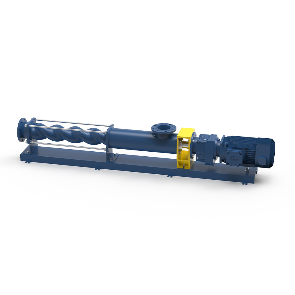 Equal Wall Thickness Screw PumpsEqual-wall stator design reduces uneven heating and supports higher stage pressures in the same shell size; useful when comparing stage counts against required discharge pressure.View Product →
For anyone comparing stage counts against a required discharge pressure, it is worth reading the background on constant wall thickness design before finalising a model selection, because the difference between an even and an uneven wall shows up in stator life rather than in the datasheet headline.
Flow comes from cavity volume and speed, pressure comes from stage count, and stator life comes from interference and wall uniformity, all three are visible on the drawing.
Wear does not spread evenly through a progressive cavity pump, because only a few components sit in the loaded path. The parts diagram shows which components carry the torque chain and which ones simply contain the fluid, and service records show how often each one is asked for.
The chart below is a relative index rather than an absolute figure. It reflects how frequently maintenance teams replace each item on a pump that handles mildly abrasive sludge or viscous process fluid, with the stator set at 100 as the reference point.
Relative replacement demand index for progressive cavity pump wear parts in abrasive or viscous duty, stator indexed at 100.
The stator dominates because it is the only component that is designed to be compressed. Its rubber does the sealing work, absorbs the abrasive particles that pass through the cavities, and swells or hardens depending on the fluid. A stator running in clean water can last years; the same stator running in a paper stock with sand contamination may not last a season.
The rotor sits second on the list because it is protected by the rubber until the interference disappears. Once the stator wears and the squeeze is lost, the rotor begins to contact the stator wall directly, and hard chrome or a coated surface starts to pick up scoring. That is why replacing a stator on schedule is usually cheaper than replacing rotor and stator together.
Seals, joints and extension shafts follow in the wear order. Packing sets and mechanical seals degrade from the same abrasives that attack the stator, and the universal joint or coupling rod carries the full drive torque in a constantly changing angle. Extension shafts are usually replaced because of spline wear or because a new rotor came with a different head connection rather than because the shaft itself has failed.
 Stator for Progressive Cavity PumpsA replacement stator matched to the original drawing helps avoid repeat failures; custom rubber formulations can suit changing process fluids better than a stock item.View Product →
Keeping a spare stator matched to the original drawing, rather than to a substitute that looks similar, is the single most effective way to avoid repeat failures. Where the process fluid varies through the year, a compound that suits the summer duty may not suit the winter duty, and a stator made from a custom rubber formulation is often a better answer than a stock item.
If a maintenance budget allows only one spare, make it the stator, because it protects every other part in the drive chain.
The longitudinal section is where the flow path becomes visible. Fluid enters the open suction chamber, which is deliberately larger than the cavity cross-section so that the first cavity fills completely even with a viscous product. From there the cavities progress axially along the stator, each one sealed from the next by the interference line, and discharge at the far end without any check valve or pulsation damper.
This is the reason a progressive cavity pump handles things that centrifugal and rotary lobe pumps cannot. Because the flow is axial and the shear rate is low, the pump moves sludge with fibrous solids, shear-sensitive polymer solutions, and fluids with viscosities that would stall a centrifugal impeller. The trade-off is equally visible on the drawing: the cavity geometry is fixed, so flow is almost directly proportional to speed, and pressure is limited by how many stages you are willing to buy.
The seal arrangement at the drive end is drawn in the same view and deserves as much attention as the rotor and stator. Four arrangements appear most often: gland packing for dirty or intermittent duties, a single mechanical seal for clean fluids, a cartridge seal for easier replacement, and a double or quench seal where the pumped fluid must not reach the atmosphere or must be flushed because it crystallises or solidifies when it cools.
Where the drawing shows flush or quench ports, they are not decoration. A quench connection that is capped off during commissioning will show up later as a failed seal face and a contaminated product line. It is worth confirming the seal plan against the actual fluid before the pump is piped, not after.
The longitudinal view shows why a progressive cavity pump is gentle on solids and shear-sensitive fluids, and the same view shows which seal ports must be connected.
Once the layout is familiar, the next step is to read the dimensions and their tolerances. Most catalogues show nominal figures, but the sheet that governs whether a replacement part fits shows tolerances. Two stators from different suppliers can both claim a bore of 60 mm and still differ by more than the squeeze allowance once the tolerance band is applied.
A practical habit is to record the dimensions that matter for interchangeability before any purchase order is raised. The table below lists the numbers that are most often requested during a replacement enquiry, along with the reason each one matters.
| Dimension or feature | Common notation | Why it matters |
|---|---|---|
| Rotor eccentricity | e | Sets the cavity volume and the squeeze against the stator bore |
| Rotor pitch and stator lead | P and 2P | Determines how quickly cavities progress and therefore flow per revolution |
| Stator tube outer diameter | OD | Must clear the casing and match the flange or clamp connection |
| Stator free length | L | Controls stage count, pressure capability and rotor shaft length |
| Rotor head connection | Pin, threaded or welded | Decides whether a new rotor will fit the existing coupling rod |
| Extension shaft spline | Count and pitch | Must match the drive end and the rotor head simultaneously |
| Elastomer hardness | Shore A | Affects interference, heat build-up and tolerance to abrasives |
Tolerance practice varies by component. Rotor diameters are usually held tightly because the metal is machined and coated, while stator bores have a wider band because rubber moves after moulding and again after the first few hours of running. A stator measured straight out of the crate may read slightly small; a stator measured after a week of operation will read differently again.
This is also why drawings sometimes show a stator with an oval or irregular appearance. It is not a drafting error. The bore is deliberately shaped so that the interference is distributed around the rotor orbit, and a stator that looks perfectly round in a drawing is usually a simplified illustration rather than a manufacturing specification.
Nominal dimensions confirm the pump size, but only tolerances confirm that a replacement part will actually seal.
A drawing describes geometry, and geometry alone does not describe behaviour. Two pumps with identical cross-sections will behave differently on a thin solvent and on a thick sludge, and the difference is not visible in the section view. That is what the performance curve is for.
Three effects sit entirely outside the drawing. The first is slip, the internal leakage that increases as discharge pressure rises and viscosity falls, which is why a pump rated at a nominal flow will deliver less at the top of its pressure range. The second is viscosity correction, since a thick product fills the cavities more completely and reduces slip, which is why the same pump can look slightly better on heavy fluid than on water. The third is temperature, which softens or hardens the elastomer and changes the interference while the pump is running.
There is also the question of solids. A drawing can show a rotor and stator, but it cannot show whether the largest particle in the stream will pass through the cavity opening without being crushed against the rubber. As a rule of thumb, the largest acceptable soft particle is a fraction of the cavity cross-section, and hard particles should be smaller still, but the only reliable answer comes from matching the drawing against the actual fluid analysis.
For applications where pressure and flow both have to be right, the sensible approach is to read the diagram for fit and the curve for duty, then confirm both against the fluid data. A pump that is geometrically perfect but hydraulically undersized will still disappoint, and a pump that is hydraulically correct but dimensionally wrong simply will not fit.
Use the diagram for fit, the curve for duty and the fluid analysis for materials, no single sheet answers all three questions.
For a buyer, the diagram is where specification becomes money. Material selection is normally annotated directly on the section view or on the accompanying parts list, and the choices have real cost consequences. Casings may be cast iron, stainless steel or duplex, stators may use nitrile, EPDM, HNBR, fluoroelastomer or a white food-grade compound, and rotors may be stainless with a hard chrome layer, ceramic coated or treated with a hardened surface for abrasive duty.
Interchangeability is the other commercial question. Because the stator is a moulded rubber tube with a flange or clamp at each end, it can often be matched to pumps from other manufacturers if four values line up: tube outer diameter, free length, flange bolt pattern and stator lead. Where the lead matches, a replacement stator from a different source will run in the same pump, which is why the drawing and not the brand name is the real specification.
This is also the point at which custom compounds earn their place. Standard nitrile works well on water-based slurries and mild chemicals, but it swells in ketones and aromatics. EPDM handles hot water and many acids but not mineral oils. HNBR tolerates higher temperatures and better abrasion, and fluoroelastomer covers aggressive chemical duty at a higher cost. A supplier with its own rubber formulation capability can adjust hardness and resilience for a specific mixture rather than forcing a stock compound into an application it was never designed for.
Scale matters as well. A maintenance team replacing one stator and a project buyer ordering pumps for a new treatment line are working from the same drawing but with different expectations of lead time and documentation. A manufacturer used to working with both tends to keep the same drawing conventions and part numbering across small and large orders, which removes a great deal of confusion at the point of reordering.
Match outer diameter, free length, flange pattern and lead, and a stator or rotor can be sourced on geometry rather than on brand.
Most ordering errors come from a small set of repeated mistakes. They are easy to avoid once you know which ones they are.
Each of these mistakes costs either a return shipment or a shutdown. Checking four or five dimensions with a caliper against the drawing takes ten minutes and removes nearly all of the risk.
Measure the part you have and compare it to the dimensions on the sheet, never to the part number printed on a worn nameplate.
With a usable drawing in hand, a spare parts list almost writes itself. Work through the torque path from the drive end to the suction end and record one dimension for each component, because that is the order in which the parts are removed and the order in which failures travel.
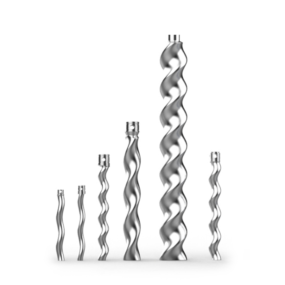 Single Screw RotorSingle screw rotor for progressive cavity pumps, where head connection and overall length govern fit; check rotor and stator as a pair when replacing worn parts.View Product →
A rotor is often the part where measurement goes wrong, because coating thickness and slight surface wear change the effective diameter. The dimension that governs fit is the head connection and the overall length; the running diameter should be compared against the nominal figure for the model rather than against a worn original. Where the rotor is to run with a new stator, both should be checked as a pair so that the interference is correct from the first start.
It also helps to keep a small record for each pump: model, serial number if available, stator tube outer diameter, stator length, lead if known, rotor head type and the fluid being pumped. Once that record exists, ordering a replacement becomes a matter of one email rather than a day of measurements, and the risk of a wrong part arriving on site falls sharply.
Record four numbers per pump, tube outer diameter, stator length, lead and rotor head type, and you will never need to guess at a replacement again.
Selection rarely ends at the catalogue. A pump that handles a specific slurry at a specific temperature is usually a small variation on a standard model, and the difference between a smooth installation and a troublesome one is often whether the supplier can adjust a rubber compound, a stage count or a connection detail without a long lead time.
For buyers comparing options, three practical questions sort useful suppliers from the rest. Can they draw the unit you actually need rather than only quoting a stock number? Can they supply both the complete pump and the wear parts, so that the stator, rotor and extension shaft all come from the same geometry? And can they hold that geometry consistently across repeat orders, so that the third stator you buy is identical to the first?
Browse the full range of single screw pumps and their matched spare parts in one place:
Because geometry is the specification, a manufacturer that keeps its own drawings, rubber formulations and machining tolerances in-house can answer dimension questions directly rather than referring them elsewhere. That is also what makes a spare parts programme work over several years, since the stator ordered in the second year of operation still matches the rotor installed in the first.
For projects that span several sites, the same principle applies at a larger scale. Consistent dimensions let a maintenance team standardise its spares across a plant, and consistent documentation lets a purchasing department compare quotations on equal terms.
The best test of a progressive cavity pump supplier is whether the second stator they ship is dimensionally identical to the first.
A specification sheet lists flow, pressure, power and connection sizes. A progressive cavity pump diagram shows the geometry behind those figures: rotor eccentricity, stator lead, the interference that seals each cavity, and the position of seals and ports. Two pumps can share identical performance figures and still take completely different spare parts, because their internal geometry differs.
Five values are normally enough. Measure the tube outer diameter, the free length, the flange or clamp pattern, the bore if the stator is accessible, and the lead if it can be determined. With those values, a stator can usually be matched even if the original manufacturer is unknown or the pump nameplate is unreadable.
Frequently yes, provided the outer diameter, free length, end connection and lead all correspond. The stator is a moulded rubber element in a metal tube, not a proprietary assembly, so the dimensional match matters more than the brand name. It is always worth confirming the lead, because a stator with identical outer dimensions but a different pitch will not seal correctly against the existing rotor.
A cross-section cuts the pump through one plane and shows fit, interference and wall thickness, which is what you need for diagnosis and for checking whether a replacement will seal. An exploded view separates the components along the axis and shows assembly order and connections, which is what you need for a spare parts list or for training a maintenance team. Most practical decisions need both.
Stage count appears in the longitudinal section as a series of repeating cavity divisions along the stator. Each stage adds a fixed pressure increment, so the number of stages follows directly from the required discharge pressure and the pressure capability of the chosen elastomer. Higher pressure duty generally means more stages, a harder compound or a thicker stator wall rather than a faster running speed.
It depends on the fluid, the temperature and the solids. Nitrile covers many water-based and oily duties, EPDM suits hot water and many acids, HNBR handles higher temperatures and abrasion better, and fluoroelastomer covers aggressive chemicals at higher cost. Where the fluid is a mixture or the temperature swings, a custom compound matched to the actual duty is usually more economical over a full service interval than a stock item that fails early.
Not strictly, but you need the equivalent measurements: overall length, head diameter and connection type, running diameter and surface treatment. A rotor that is dimensionally correct but fitted with the wrong head connection cannot be installed, and a rotor with an incorrect coating will wear faster than the stator it is meant to protect.
There is no universal figure, because life depends on the fluid, the speed, the discharge pressure and the amount of abrasive material passing through. What the drawing does allow is comparison. If a stator that previously ran for two years now fails in six months, the geometry has probably not changed but the duty has, and checking the interference, the compound and the operating pressure usually explains the difference.
A progressive cavity pump diagram is a maintenance tool as much as a design document, and the teams that read it early spend less time rebuilding pumps and more time running them.
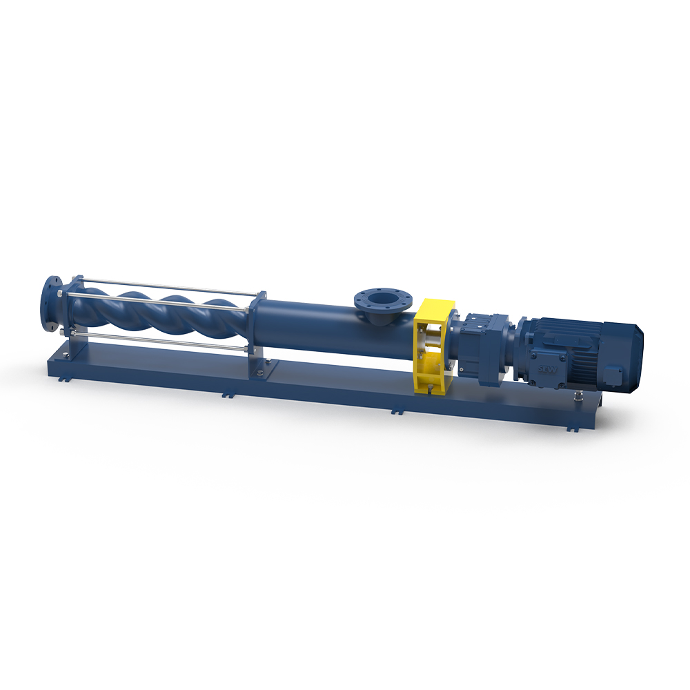
Screw pumps equipped with equal wall thickness stator, the same kind of pump specifications pump flow, and pressure are increased. The equal wall thic...
See Details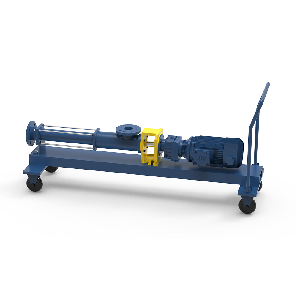
Mika vehicle-mounted pump, the pump base is not only stable and reliable, but also cleverly equipped with universal wheels, these wheels rotate flexib...
See Details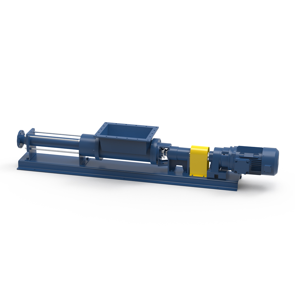
The inlet is a large hopper design W-type pump with a connecting shaft with multiple spiral vanes (which can effectively prevent the accumulation of m...
See Details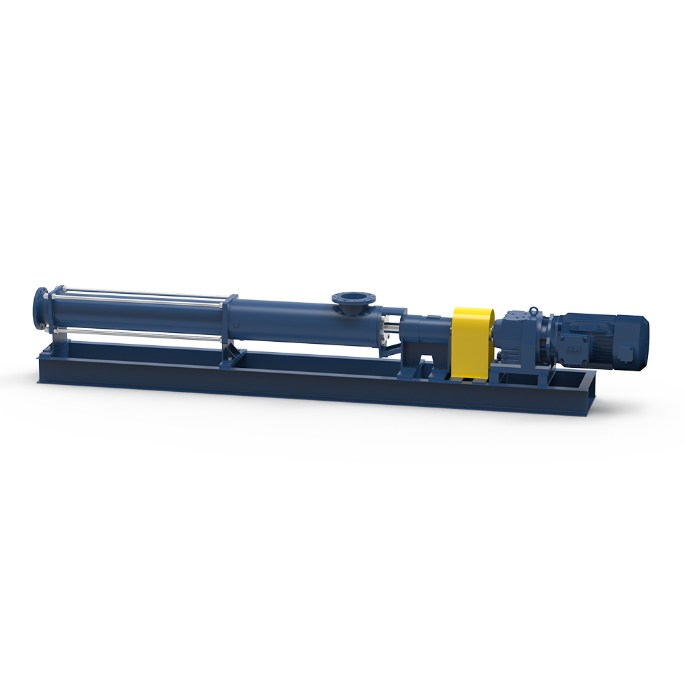
The S-pump with bearing frame support can withstand higher axial loads and can be used for high-pressure conditions, e.g. high-pressure sludge feed tr...
See Details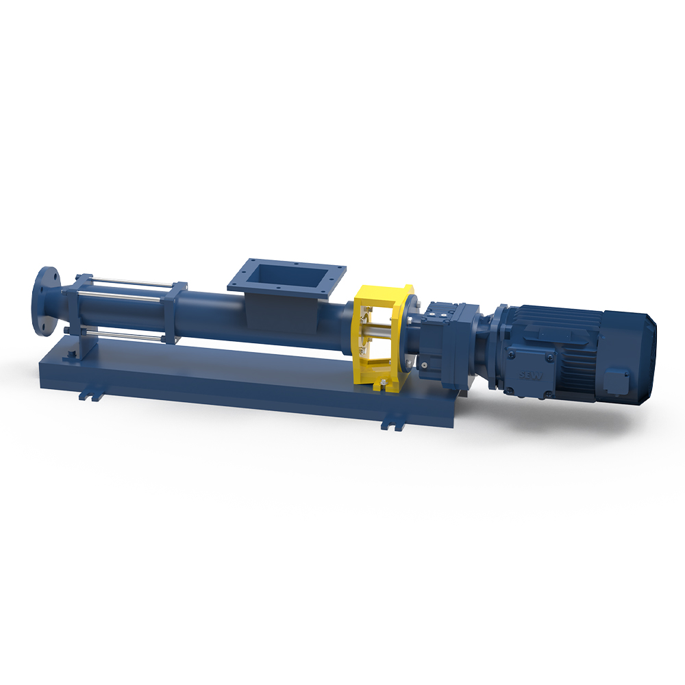
The inlet is a small rectangular hopper design H pump, suitable for conveying high viscosity solid content of less than 15% of the medium, such as cru...
See Details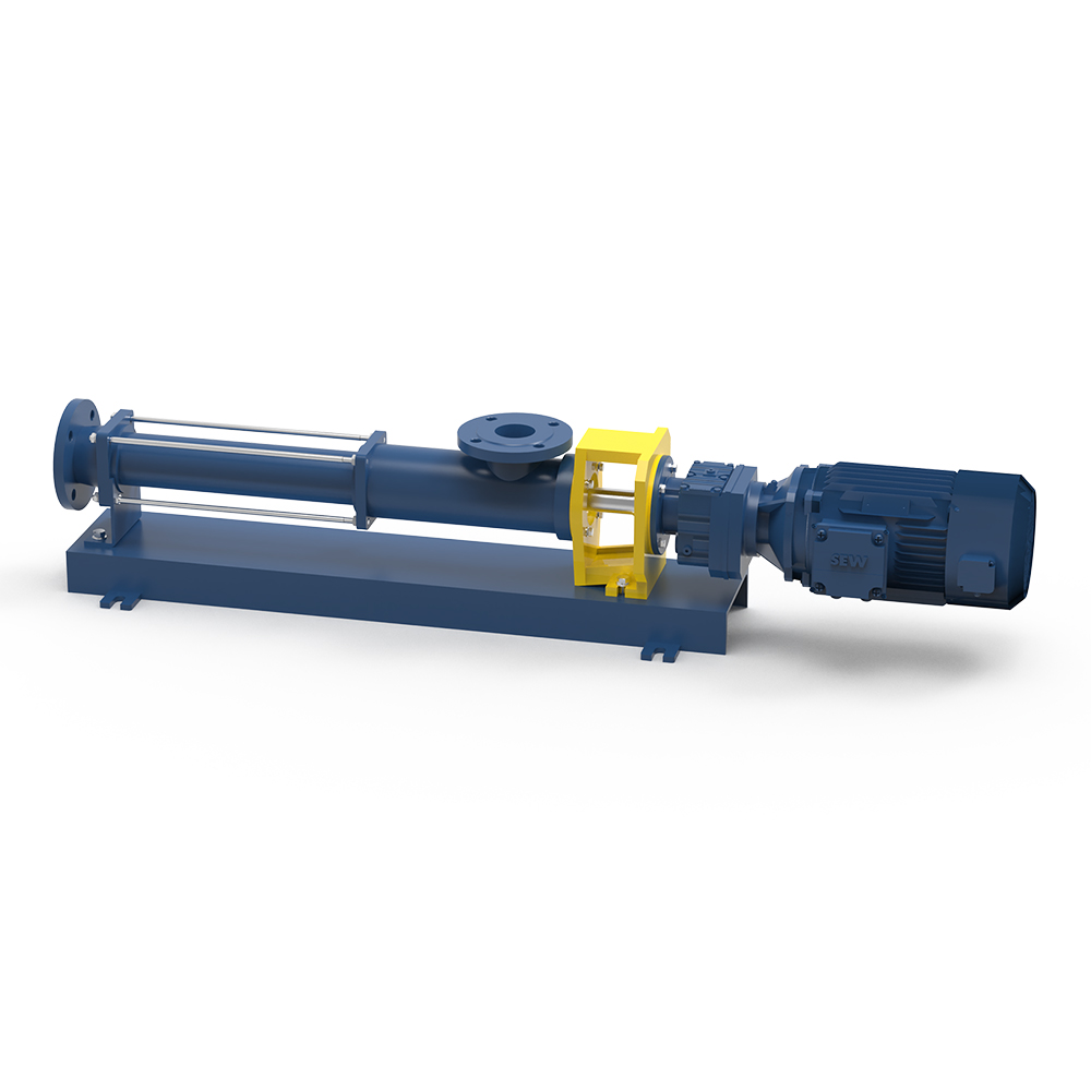
Mika Classic B direct-connected pumps are compact, easy to maintain, with low investment costs, and are suitable for a wide range of common working co...
See Details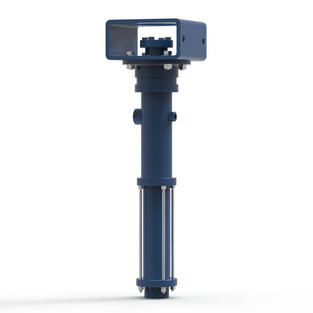
Precise flow rates and a wide range of materials for the metering and delivery of all kinds of sealants. Working Principle The MeiJia pump is a prog...
See Details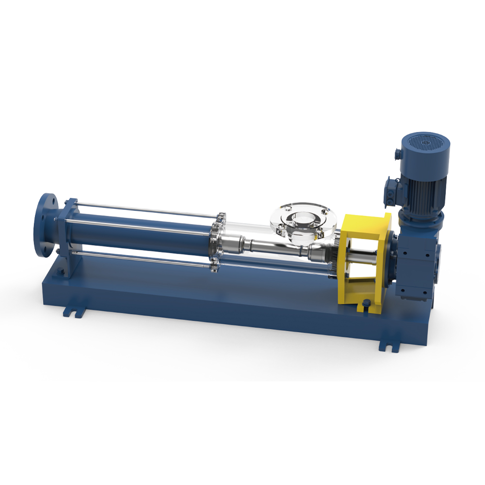
The speed reducer adopts the K series speed reducer, and the length of the pump can be shortened, so it can be used in places where the space is narro...
See Details
Various materials are available for different working conditions, such as NBR, HNBR, EPDM, and FKM.
See Details
Multiple materials available: Q235,304,316L,2205,2507, etc.
See DetailsContact Us
Add: No. 36 Xintai Road, Economic Development Zone, Jingjiang City, Jiangsu Province, China
Tel: +86-13515167342
Fax: +86-523-84261117
E-mail: [email protected]
We'd love to
hear from you!
